برای طراحی تابلو خازنی شما ابتدا باید برآورد صحیحی از ظرفیت بانک خازنی مورد نیاز داشته باشید. برای اینکار لازم است میزان ضریب توان مطلوب که آن نیز از برآوردهای اقتصادی برای تعیین ضریب توان اپتیمم بدست می آید، نتیجه شود. اگر میزان بار اکتیو شما P باشد، ظرفیت بانک خازنی مطلوب برای رسیدن از زاویه توان φ1 به زوایه مطلوب φ2 نیازمند ظرفیت جبران سازی معادل Qc مطابق رابط زیر خواهیم بود.
این ظرفیت می توان به طور یکجا برای جبران سازی اثر یک ترانس یا موتور الکتریکی به سیستم اعمال شود و یا اگر توان P شامل یک گروه از بارهای جزئی تر مانند موتورهای الکتریکی کوچکتر است، مقدار ظرفیت جبران سازی می تواند بصورت پلکانی از طریق رله تنظیم کننده مخصوصی که بطور اتوماتیک بانکهای خازنی جزئی را وارد مدار می کند، به سیستم اعمال شود.
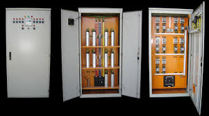
به برخی ملاحظات فنی در خصوص تابلو و طراحی تابلو خازنی و طراحی سیستم جبران ساز اتوماتیک برگرفته از یکی از هندبوکهای تأسیسات الکتریکی توجه کنید.
Since compensating system devices is also associated with the same power system as a switchgear assembly, it should generally meet the same specifications except for small variations in operating conditions and test requirements. Capacitors generate excessive heat when in service. Installations employing large capacitor banks must therefore have a capacitor mounting structure suitable to dissipate heat freely and permit circulation of fresh air during normal operation. To achieve this, open-type enclosures are usually preferred when it is possible to house the panel in a separate room or mount the units on a structure in an open switchyard. It may also be provided with an expanded metal enclosure. Forced cooling within the enclosure or the room where such banks are installed is common practice to dissipate the excessive heat. For more details refer to the following publications:
IEC 6083 1 – 1 and 6093 1 – 1 for LT, and IEC 6087 1 – 1 and
IEC 60143- 1 for HT systems
When selecting the voltage of the capacitor units care must be taken that during operation the voltage across the capacitor units does not fluctuate beyond +/- l0%. If this happens the voltage rating of the capacitor units must be chosen so that the variation across the units under unfavorable operating conditions does not exceed
+/- l0%.
Automatic PF correction of a system
For an industrial or power plant application or an installation with a number of inductive load points a group capacitor control is always more effective, simple and economical. Such an installation generally has a frequent variation in its load demand due to some feeders coming on the bus and some falling out at different times. There may be variation in the individual feeder’s load demand, such as a tool room, where not all the machines will be working at a time, or a pulp mill and paper mill, where the paper mill has a continuous load, the pulp mill an intermittent one. A water treatment plant or a pump house are similar installations where all or some of the loads would be in operation at a time. For such installations, the total capacitive load demand at a required power factor level is worked out and the total capacitor banks are installed at a convenient point and suitably grouped (banked) for the type of loading and system demand. Each bank is controlled through a power contactor and a common power factor correction relay to automatically monitor and control the power factor of the system to a predetermined level, preset in the relay, by witching a few capacitor banks ON or OFF, depending upon the load demand and the power factor measured by the relay. The relay actuates the required number of capacitor feeders through their contactors.
Automatic correction is always recommended to eliminate manual dependence and to achieve better accuracy. It also eliminates the risk of a leading power factor by a human error that may cause an excessive voltage at the motor and the control gear terminals.
The following example illustrates the method of selecting the capacitors’ value, their grouping and their control for a system having a number of load points.

A switching sequence that can be employed for a particular load cycle may be one of the following: First in last out
This is the simplest type of switching. Capacitors are switched ON in the sequence of 1-2-3 . . . n and switched
OFF in the reverse sequence i.e. n . . . 3-2-1. In this switching the last switched capacitor is made to switch again. This switching is therefore more stressful for the capacitor as well as for the system, due to surge voltages.
During a switch ON therefore some time delay must be introduced into the switching circuit for the capacitor charge to decay to a safe level. In this sequence, the capacitors of each step are normally the same. It is a primitive and unscientific switching sequence and therefore not in much use.
True ‘first in first out’ (FIFO)
Capacitors are switched ON in the sequence of 1-2-3 . . . . n but an additional logic is used to switch OFF in the same sequence 1-2-3 . . . n, i.e. the oldest OFF capacitor is switched ON first and the oldest ON capacitor is switched OFF first. This apparently is the best switching sequence, giving enough time to an OFF capacitor to discharge before it is switched again. Each stage capacitor rating must be equal to avoid a wide fluctuation in the p.f. correction and hence undesirable subsequent switchings, which may be necessitated when the capacitors are not of equal ratings.
Pseudo (false) ‘first in first out’
In a way this is more appropriate than the FIFO, for it can have unequal stage capacitors. Capacitors, however, are arranged in ascending order such as 10, 20, 50 . . . kVAr etc., or large or small capacitors. But, as mentioned above, this may not provide accurate correction in the first instance. Now the relay may have to operate on the theory of probability and resort to a lot of sequencing to arrive at the right correction. Such sequencing may also lead to hunting and cause voltage fluctuations, because of varying p.f. s and also cause switching currents and voltage surges.
1+2+2. ..
The first capacitor is half the rating of the remaining ones, which are all equal. The p.f. correction is delayed, due to allowing discharge time. The smallest unit is more stressed.
Direct combinatorial or auctioneering
Here the relay assesses the kVAr requirement of the system and switches ON all the required capacitors simultaneously. Theoretically any size of capacitor units can be used. But when a capacitor is taken out for maintenance, this can create confusion in the p.f. correction. The relay will not be aware of this and act accordingly. The bank size may also be large and cause switching surges.
Special sequencing
These are sequencers and can sequence the switching of capacitors in any fixed pattern. Capacitors can be automatically taken out of the circuit and others introduced in their place by a device known as ‘the load rotator.
A good relay can be modified to perform a particular switching sequence during ON and OFF and both sequences need not be same. The following is a type of relay that can be modified to perform any desired switching pattern.